⚠️
Essential Warning!
DO NOT begin any of the procedures in this guide unless you are fully qualified, electrically competent, and familiar with safe isolation practices.
Working on immersion heaters involves exposure to
230V live electrical components, which can cause serious injury or death if handled incorrectly.
If in doubt—stop and call a licensed electrician or heating engineer.
Introduction
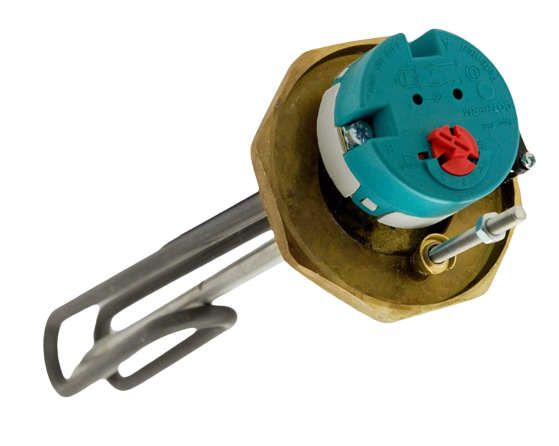
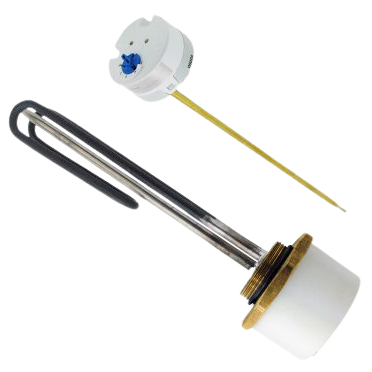
Immersion heater elements are simple resistive heating coils housed inside a copper or Incoloy sheath.
When they fail, it often presents as:
- No hot water
- Tripping MCBs or RCDs
- Overheating
- Visible damage or leaks around the immersion boss
Before replacing the immersion element, a few basic tests can help confirm whether it has failed. These tests assume you have already confirmed
power is reaching the immersion heater through the thermostat.
How to Test an Immersion Element
1.
✔
Isolate the Electrical Supply
Before anything else:
- Switch OFF the local fused spur or isolation switch
- Remove the fuse if applicable
- Lock off and label if required
- Verify dead
using an approved voltage tester
Never trust that a switch "looks" off—always test!
2.
✔
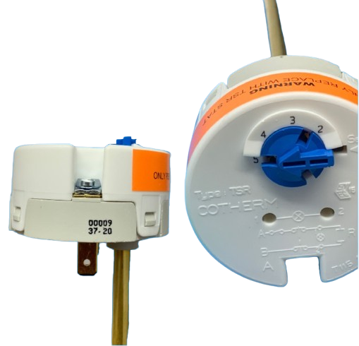
Remove the Cover Cap
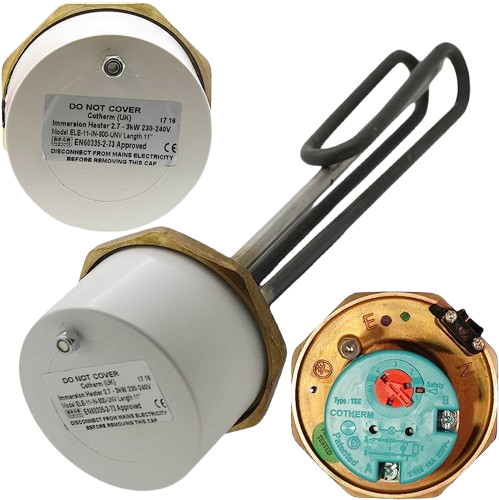
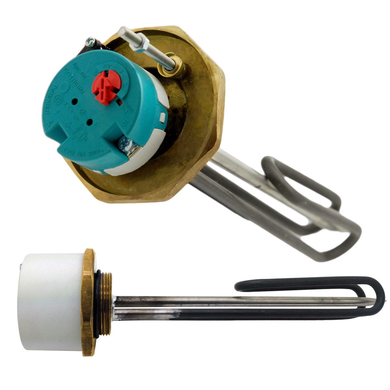
Remove the immersion cover to expose the thermostat and terminals.
- Cotherm thermostats typically use an
8 mm nut, although adjustable pliers will work.
- After removal, you will see the thermostat inserted into the immersion boss.
Optional but recommended:
Remove the thermostat
to test it separately.
(See our previous thermostat-testing blog)
You are now looking at the bare immersion chassis boss with two terminals.
3.
✔
Visual Inspection
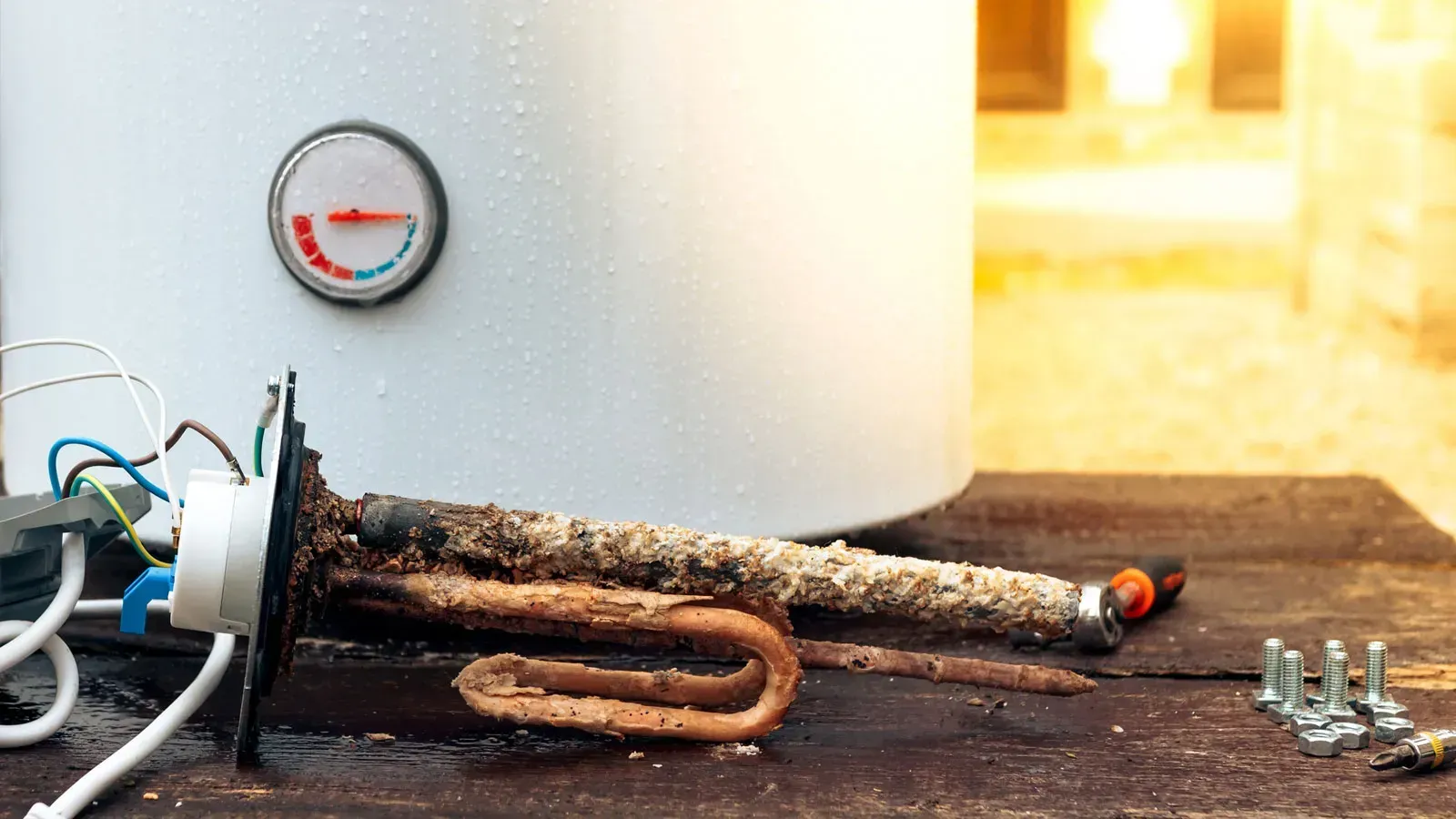
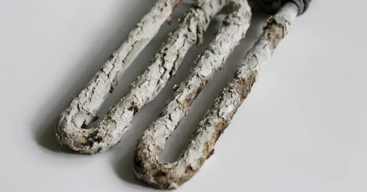
Before testing electrically, check for signs of:
Water ingress
- Water marks
- Drips
- Corrosion around terminals
This often indicates a failed immersion gasket
Burn marks or scorching
- Blackened or melted terminals
- Smell of burning
This may indicate loose connections or overheating.
Mechanical damage
- Bent or badly fitting terminals
- Cracked ceramic supports
- Damaged brass housing
Any of these signs strongly suggest replacement is needed.
4.
✔
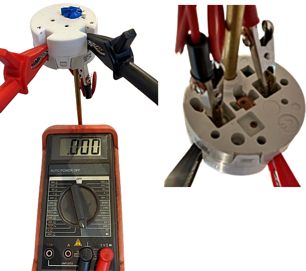
Electrical Continuity Test (Element Resistance Test)
The immersion element is simply a resistive heating coil.
A standard 3 kW element should measure around 18–20 Ω.
How to test:
- Set your multimeter to
continuity or the
2 kΩ resistance range.
- Place one probe on
each immersion terminal.
Expected results:
- Continuity tone or a stable reading close to 19 Ω → Element is likely functional
- No continuity or infinite resistance (Open circuit) → Element has failed
- Very low resistance (near 0 Ω)
→ Internal short → Replace immediately
- Significantly higher than 20–25 Ω → Element is failing or partially burnt out
This is the core test to confirm element failure.
FOR CLARITY - SEE IMAGES BELOW!
5.
✔
Alternative Combined Test – Linking the Spade Connectors
An alternative method is to:
- Link the thermostat’s spade connectors
- Test continuity across the main A & B supply terminals
This helps confirm:
- No breaks in the thermostat connections
- Safety cut-out hasn’t tripped
- Wiring continuity through the thermostat line
This is especially useful when diagnosing intermittent or thermal-related issues.
FOR CLARITY - SEE IMAGES BELOW!